CoreStation 20 Setup and Door Creation
CoreStation 20 (CS-20/CS-20P) is Suprema's new controller that enables easy implementation of two-door access control.
Compared to the existing four-door model, CoreStation (CS-40), it is lighter and optimized for RFID card-based access control.
It can store up to 500,000 user infomation and supports compatibility with various interfaces.
In particular, the CS-20P model supports easy installation with PoE+ (Power over Ethernet) and is equipped with a SAM card slot for enhanced security.
This document provides an overview of the CoreStation 20 menu in BioStar 2 and explains how to create doors.
-
CoreStation 20 does not support wireless door locks.
-
CoreStation 20 does not support biometric authentication (such as face or fingerprint); only card authentication is supported.
If biometric authentication is required, it is recommended to use CoreStation (CS-40).
Detailed Device Settings
-
Click DEVICE.
-
In the device list, select the CoreStation 20 (CS-20/CS-20P) you want to configure.
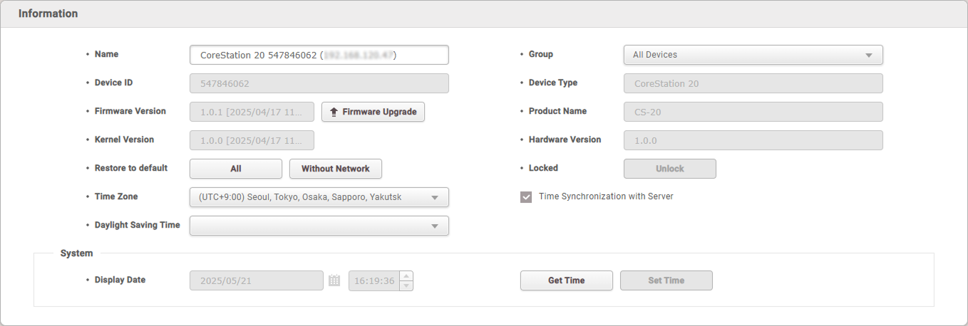
Device Information
-
Name: Enter the desired device name.
-
Device ID: The device ID appears.
-
Firmware Version: Click Firmware Upgrade to install a new firmware version.
-
Kernel Version: You can check the kernel version.
-
Restore to default: You can initialize the device settings. Click All to initialize all settings, or click Without Network to initialize all settings except for the network configuration.
-
Time Zone: Set the device's time zone. The device time zone can be set differently from the BioStar 2 server time zone.
-
Daylight Saving Time: Apply the daylight saving time set by the user to the device. New daylight saving time can be added in Settings → DaylightSaving Time.
-
Group: You can change the device group. Device groups can be added by right-clicking All Devices in the Device menu and selecting Add Device Group.
-
Device Type: The device type appears.
-
Product Name: You can check the model name.
-
Hardware Version: You can check the hardware version.
-
Locked: If the device is locked due to trigger & actions, click the Unlock button to unlock it.
-
Time Synchronization with Server: Select this option to synchronize the device time with the server.
System
-
Display Date: Click
 to manually set the date and time. If Time Synchronization with Server is enabled, you cannot manually set the date or time.
 -
Get Time: Click to retrieve the time set on the device.
-
Set Time: Click to apply the time set in BioStar 2 to the device.
Network Settings
TCP/IP, DHCP, IP Address, Subnet Mask, Gateway, DNS, etc. Basic network settings are supported.
RS485 port can only be used in Master mode.
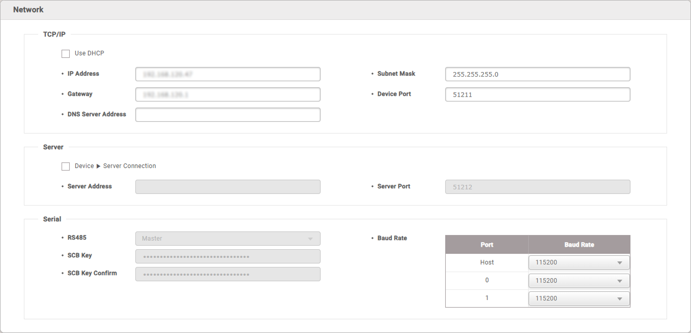
TCP/IP
-
Use DHCP: Check this option to configure the device to use a dynamic IP address. If this option is selected, a static IP address cannot be assigned.
-
IP Address, Subnet Mask, Gateway: Enter the network information if you want to assign a static IP address to the device. Make sure to uncheck Use DHCP before entering these values.
-
Device Port: Enter the port number that the device will use. This port is used for communication between BioStar 2 and the device.
-
DNS Server Address: Enter the DNS server address.
Server Communication
-
Device ▶ Server Connection: Select this option to configure the BioStar 2 connection information for the device. When selected, you can enter the network information for BioStar 2.
-
Server Address: Enter the IP address of BioStar 2.
-
Server Port: Enter the port number of BioStar 2.
Serial Communication
-
RS485: Only master mode is supported.
-
Baud Rate: Set the baud rate for each RS-485 port.
-
SCB Key: Set the SCB key for the device. This menu is only enabled when there are no RS-485 devices connected to CoreStation 20.
-
SCB Key Confirm: Confirms whether the entered SCB key matches. This menu is only enabled when there are no RS-485 devices connected to CoreStation 20.
SCB Key can be entered up to 16 bytes.
Authentication Settings
Supports card authentication related settings such as Server Matching, Card Type(CSN Card, EM4100, Mifare/Felica), Byte Order, and Format Type.
CoreStation 20 does not support biometric authentication (such as face or fingerprint); only card authentication is supported.
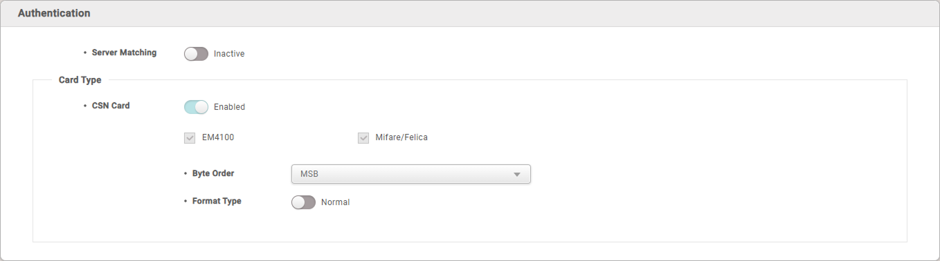
- Server Matching: If set to Active, authentication is performed using the user information stored on the PC where BioStar 2 is installed. If set to Inactive, authentication is performed using the user information stored on the device. When using server matching, BioStar 2's server matching must also be activated by enabling Use Server Matching in Settings → Server → Server Matching.
Card Types
You can set the types of cards to be used on the device.
The types of cards supported by the device are displayed.
- CSN Card: Select the CSN card and format type and set the byte order.
-
When Format Type is set to Normal, the card serial number (CSN) is read and presented without any conversion. When set to Wiegand, the device converts and presents the card serial number (CSN) according to the user-defined Wiegand format when reading a CSN card.
-
When Format Type is set to Wiegand, the Wiegand format to be used on the device is selected.
-
When Byte Order is set to MSB, card data is processed from the most significant byte to the least significant byte, and the card serial number (CSN) is proceed sequentially from left to right. LSB processes card data from the least significant byte to the most significant byte and stores the card serial number (CSN) accordingly.
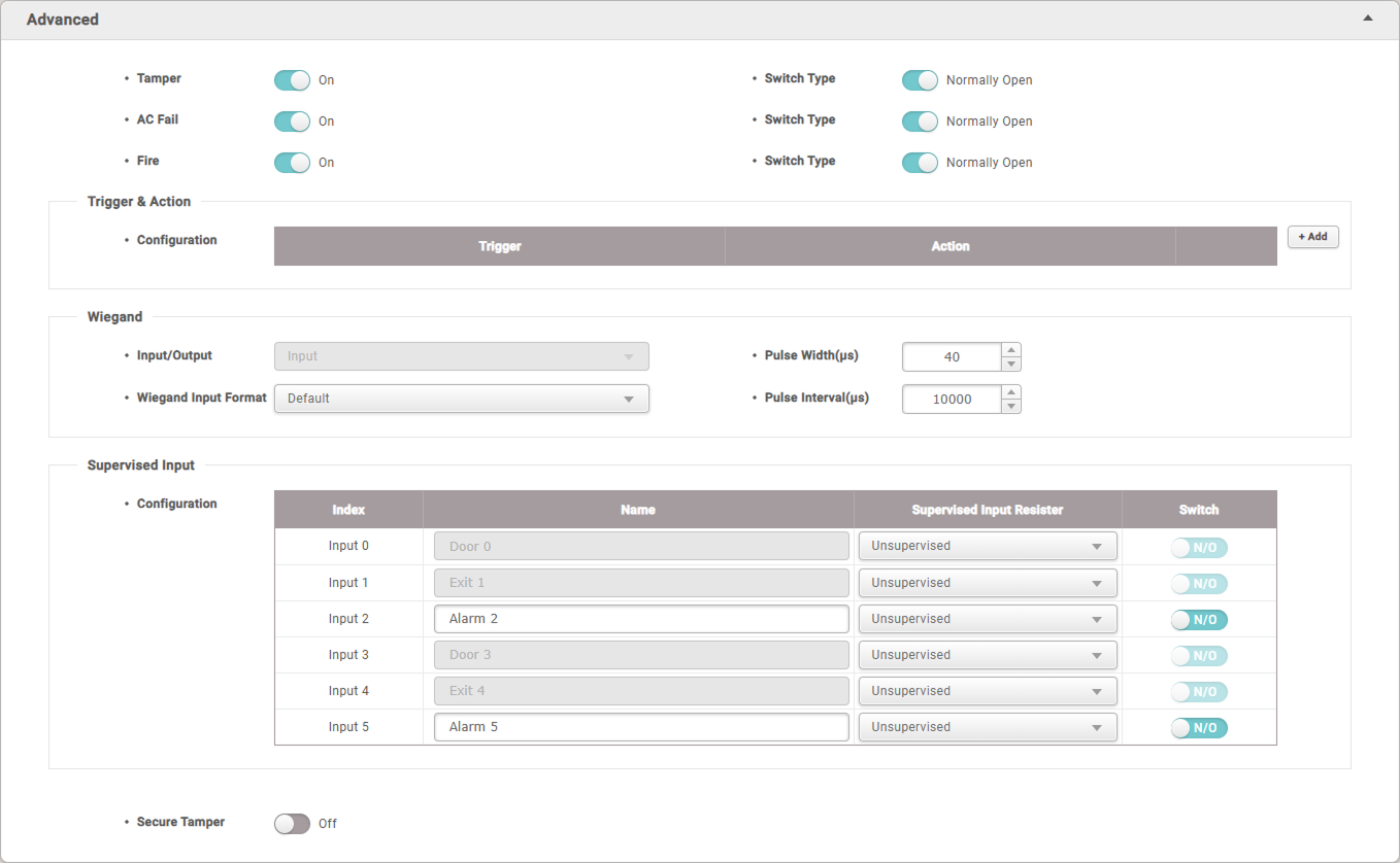
Advanced Settings
-
Tamper: Enable or disable the tamper detection feature. The tamper detection feature triggers an alarm when the device's cover is opened or the device is dropped.
-
AC Fail: Enable or disable the AC fail detection feature. The AC Fail feature triggers an alarm when the power supply is interrupted.
-
Fire: Enable or disable the fire detection feature. The fire detection feature triggers an alarm and automatically opens all doors created with CoreStation 20 when a fire is detected.
Tamper, AC Fail, Fire are automatically set to Aux Input 0~2 ports fixed for each function, so they are automatically set the feature is turned on. These ports cannot be changed by the user.
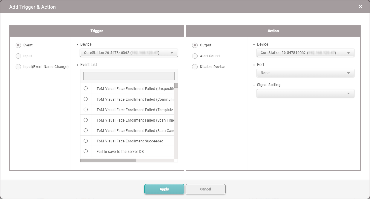
Trigger & Action
- Configuration: Set the device's actions according to predefined alarms or signal inputs.
Wiegand
-
Input/Output: Can only be used in input mode.
-
Wiegand Input Format: Change the Wiegand format assigned to the device. For details on setting the Wiegand format, refer to the card format.
-
Pulse Width(μs): Set the pulse width of the Wiegand signal.
-
Pulse Interval(μs): Set the pulse interval of the Wiegand signal.
Supervised Input
Set the Supervised Input port of the CoreStation 20 to be used as a Input port, and set the resistance value to be used for Supervised Input. The resistance values can be set to 1㏀, 2.2㏀, 4.7㏀, or 10㏀.
Secure Tamper
Set it so that when a tamper event occurs on the device, all user information, logs, and security keys stored on the device are deleted.
OSDP Reader LED/Buzzer
Uniformly set the operation of the LED and buzzer for events of all OSDP readers connected to the CoreStation 20.
If the connected OSDP reader does not support LED and buzzer, it may not operate as set.
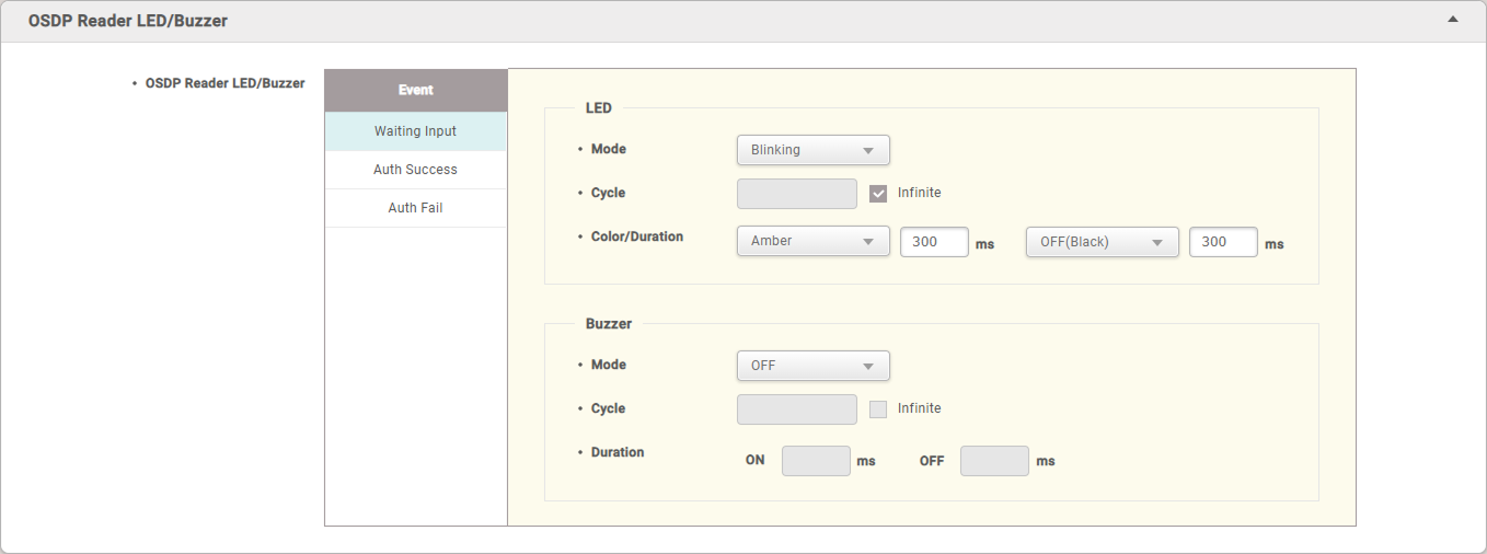
LED
Set the LED operation for events such as Waiting Input, Auth Success, and Auth Fail.
-
Mode: Set the desired action among OFF, Constant, and Blinking.
-
Cycle: If Mode is selected as Blinking, enter the number of times the LED will blink. Check Infinite to repeat the set mode continuously.
-
Color/Duration: If Mode is selected as Blinking, select two colors to blink at the set repetition rate and enter the duration. If Mode is selected as Constant, select one color to be lit and enter the duration.
Buzzer
Set the operation of the buzzer for events such as Waiting Input, Auth Success, and Auth Fail.
-
Mode: Set the desired action among OFF, Constant, and Beeping.
-
Cycle: If Mode is selected as Beeping, enter the number of times the buzzer will sound. Check Infinite to repeat the set mode continuously.
-
Duration: If Mode is selected as Beeping, enter the duration for which the buzzer will sound at each set repetition rate.
If Mode is selected as Constant, enter the duration for which the buzzer will sound.
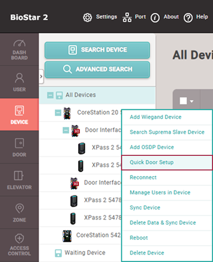
Adding Doors Using the Quick Door Setup Feature
Easily create doors by right-clicking on the connected CoreStation 20 (CS-20/CS-20P) in the device list and selecting Quick Door Setup.
-
Doors cannot be created if no slave or Wiegand device is connected to CoreStation 20.
-
Doors cannot be created if only a Door Interface is connected to CoreStation 20.
-
Click DEVICE.
-
In the device list, right-click on the device name of CoreStation 20 and click Quick Door Setup.
-
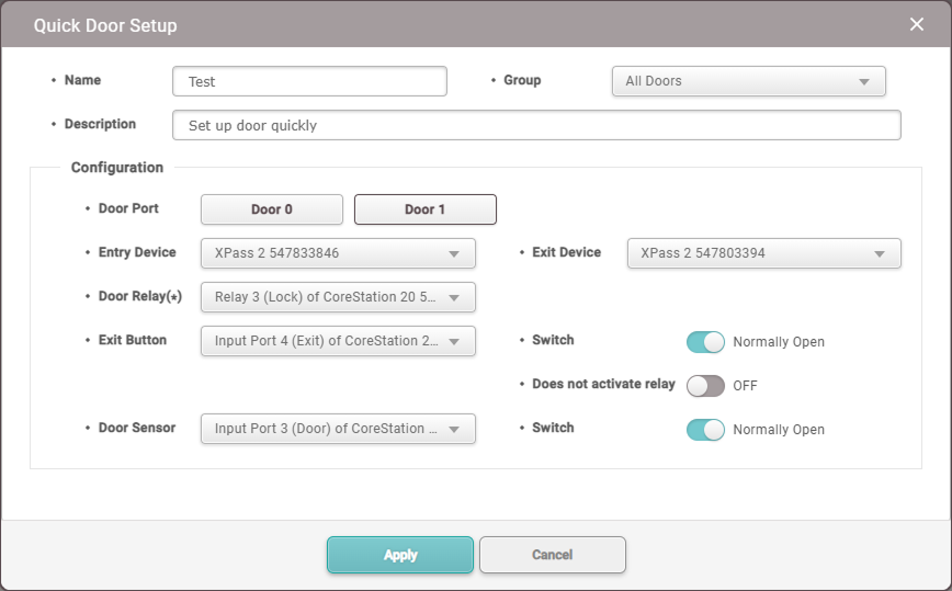
Set Name, Group, Description, and options.
Up to 2 doors can be configured using devices connected to the RS-485 or Wiegand port.
Each door is automatically assigned items such as Entry Device, Door Relay, Door Sensor, and Exit Button by port.InfoI/O devices (Door Module, Input Module, Output Module, etc.) are not automatically selected as Entry Device or Exit Device.
-
Click Apply to create the door.
Adding Doors in the Door Menu
Add doors by selecting the relay of the CoreStation 20 in the Door menu.
-
Click DOOR.
-
Click ADD DOOR.
-
Refer to Information, Configuration, Option, Anti PassBack, Timed Anti PassBack, and Alarm to configure each item.
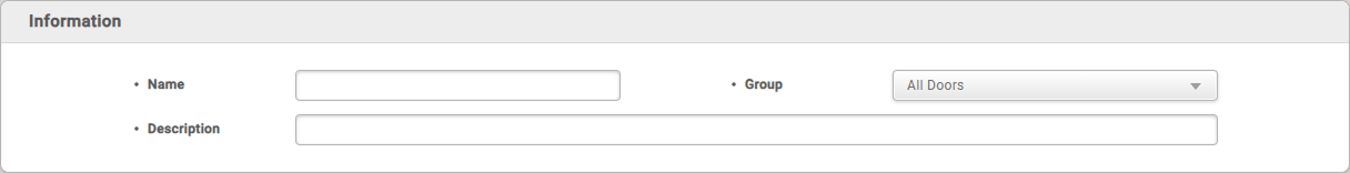
Information
Enter or change the name, group, and description of the door.
-
Name: Enter the desired door name.
-
Group: Select the door group. Door groups can be added by right-clicking All Doors in the DOOR menu and selecting Add Group.
-
Description: Enter a description of the door.
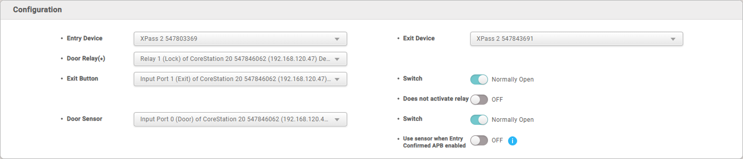
Configuration
Configure the device, relay, exit button, door sensor, and other related information.
CoreStation 20 cannot be set as an entry or exit device.
-
Entry Device: Select the device to be used for entry. Choose from the list of registered devices.
InfoCoreStation 20 does not support wireless door locks.
-
Door Relay: Select the relay that will operate the door locking device.
Info-
If select the Lock door relay, Exit Button and Door Sensor are automatically selected.
-
Alarm relay cannot be used as a door relay.
-
-
Exit Button: Select the port to be used for the exit button.
-
Switch it set to N/C or N/O.
-
Does not activate relay: Set it so that when the exit button is pressed, the door open request log is generated, but the relay does not operate.
-
-
Door Sensor: Select the port to be used for checking the door status.
-
Switch it set to N/C or N/O.
-
Use sensor when Entry Confirmed APB enabled: Set whether to use the door sensor when using the Entry Confirmed APB option.
Info-
This feature cannot be used if Timed Anti PassBack is activated.
-
If Door Sensor is set to None, the Alarm tab cannot be configured.
-
-
Exit Device: Select the device to be used for exit. The exit device must be connected as a slave device.
Info- If there is no Exit Device, the Anti PassBack cannot be set.
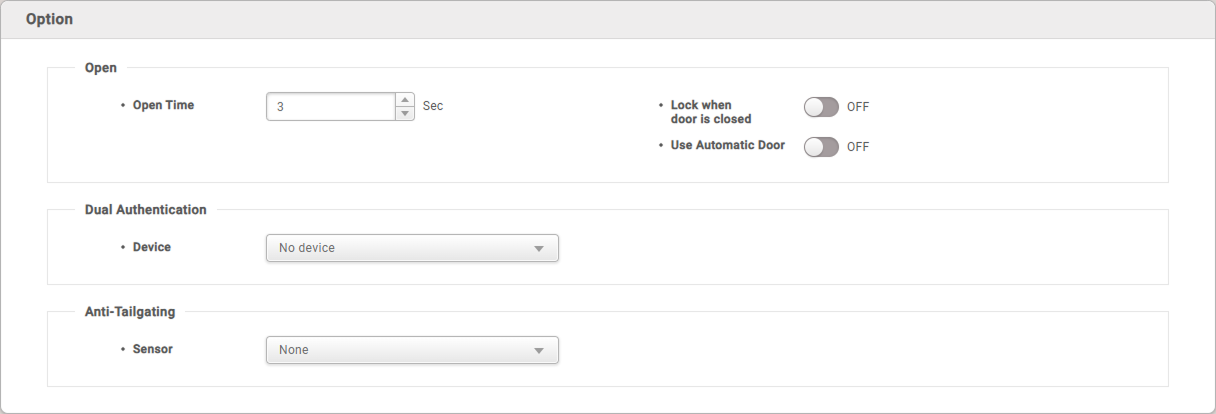
Option
-
Open: Set options for door opening.
-
Open Time: Set the time for which the door remains open after user authentication is complete. This is the time when the relay is activated after successful authentication, and after this time, the relay will no longer send a signal to the door.
InfoOpen Time may vary depending on the type of door locking device used.
-
Lock when door is closed: The door will be locked when the door sensor detects that the door is closed. This cannot be used if Use Automatic Door is set to ON.
-
Use Automatic Door: If the automatic door is to be used as the access door, the relay can operate regardless of the status of the door sensor. This cannot be used if Lock when door is closed is set to ON.
-
-
Dual Authentication: Set it so that the door opens only when two people (a regular user and an administrator) authenticate their credentials.
-
Device: Select the device to use for dual authentication. If set to No device, dual authentication mode is not used.
-
Schedule: Set the schedule for dual authentication. If there is no desired schedule, click + Add Schedule to set it.
-
Approval Type: Set the order of administrator authentication. If set to None, two authentications are required regardless of the authentication group. If set to the Last, the user authenticated as a general user, followed by the user in the set authentication group, must authenticate.
-
Approval Group: Set the group to which the administrator belongs.
-
Timeout: Set the waiting time for authenticating the second credential after the first credential is authenticated. If the second credential is not authenticated within the set time after the first credential is authenticated, the door will not open.
-
-
Anti-Tailgating : Set it to detect tailgating, where an unauthorized person follows an authorized person to gain access.
- Sensor: Select the sensor to detect tailgating.
Anti PassBack
Anti-passback is used to manage access records and enhance security.
It can prevent misuse cases where a user hands over their access card to another user after entering, and it can also prevent outsiders from following authorized users to gain access.
It can be used when both Entry Device and Exit Device are installed, and cannot be used if Exit Device is set to None.
-
To activate the anti-passback tab in the door settings, a master device and a slave device configured with RS-485 are required.
-
If Timed Anti PassBack is activated, Anti PassBack cannot be used.

-
Type: Select the type of Anti PassBack.
-
None: Select this option to turn off the anti-passback feature.
-
Soft APB: Select this option to allow access even if anti-passback is violated, but still trigger an alarm or generate a log in BioStar 2.
-
Hard APB: Select this option to prevent access when anti-passback is violated, and still trigger an alarm or generate a log in BioStar 2.
-
-
Reset Time: Set the time until the anti-passback function is reset. It can be set up to 7 days (10,080 minutes), and if set to 0, it will not be reset.
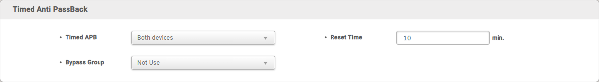
Timed Anti PassBack
Timed APB sets the time it takes for re-authentication to be possible after a user has authenticated their access, to prevent frequent re-entries.
-
Timed Anti PassBack is available without a separate BioStar 2 license.
-
Timed Anti PassBack can only be configured when either Entry Device or Exit Device and Door Relay are selected.
- As this feature is used to enhance door security, it can also be configured when only one of Entry Device or Exit Device is selected.
-
Timed Anti PassBack and Use sensor when Entry Confirmed APB enabled cannot be used at the same time.
-
Timed Anti PassBack and Anti PassBack cannot be used at the same time.
-
Select the device to use Timed Anti PassBack and set Reset Time as desired.
-
Reset Time: The input unit is minutes (min.), the default value is 10 minutes, and the available time range is 0 to 60 minutes.
InfoReset Time set to 0 minutes will deactivate Timed Anti PassBack.
-
Bypass Group: Specify the access group that can always pass without being restricted by the time-limited anti-passback.
-
-
After setting, when the Timed Anti PassBack occurs, can be view the events and Image Log in the Monitoring menu.
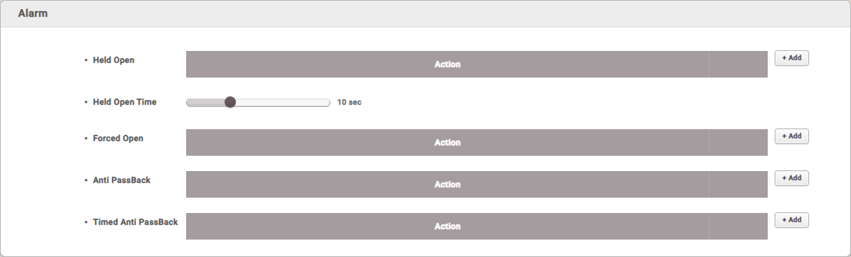
Alarm
Trigger an alarm or prevent the device from being used when the door is forcibly opened, left open, or when an anti-passback violation occurs.
-
Held Open: Set the alarm action when the door is left open.
Click + Add, then select each item. To register the set items, click Apply. -
Held Open Time: Set the time to trigger the alarm if the door is left open for a long time. This sets the maximum time the door can remain open.
-
Forced Open: Set the alarm action when the door is forcibly opened.
Click + Add, then select each item. To register the set items, click Apply. -
Anti PassBack: Set the alarm action when an anti-passback violation occurs.
Click + Add, then select each item. To register the set items, click Apply. -
Timed Anti PassBack: Set the alarm action when an timed anti-passback violation occurs.
Click + Add, then select each item. To register the set items, click Apply.InfoAnti PassBack can only be set if Exit Device is registered.
After completing all settings, click Apply to create the door.