Getting Started
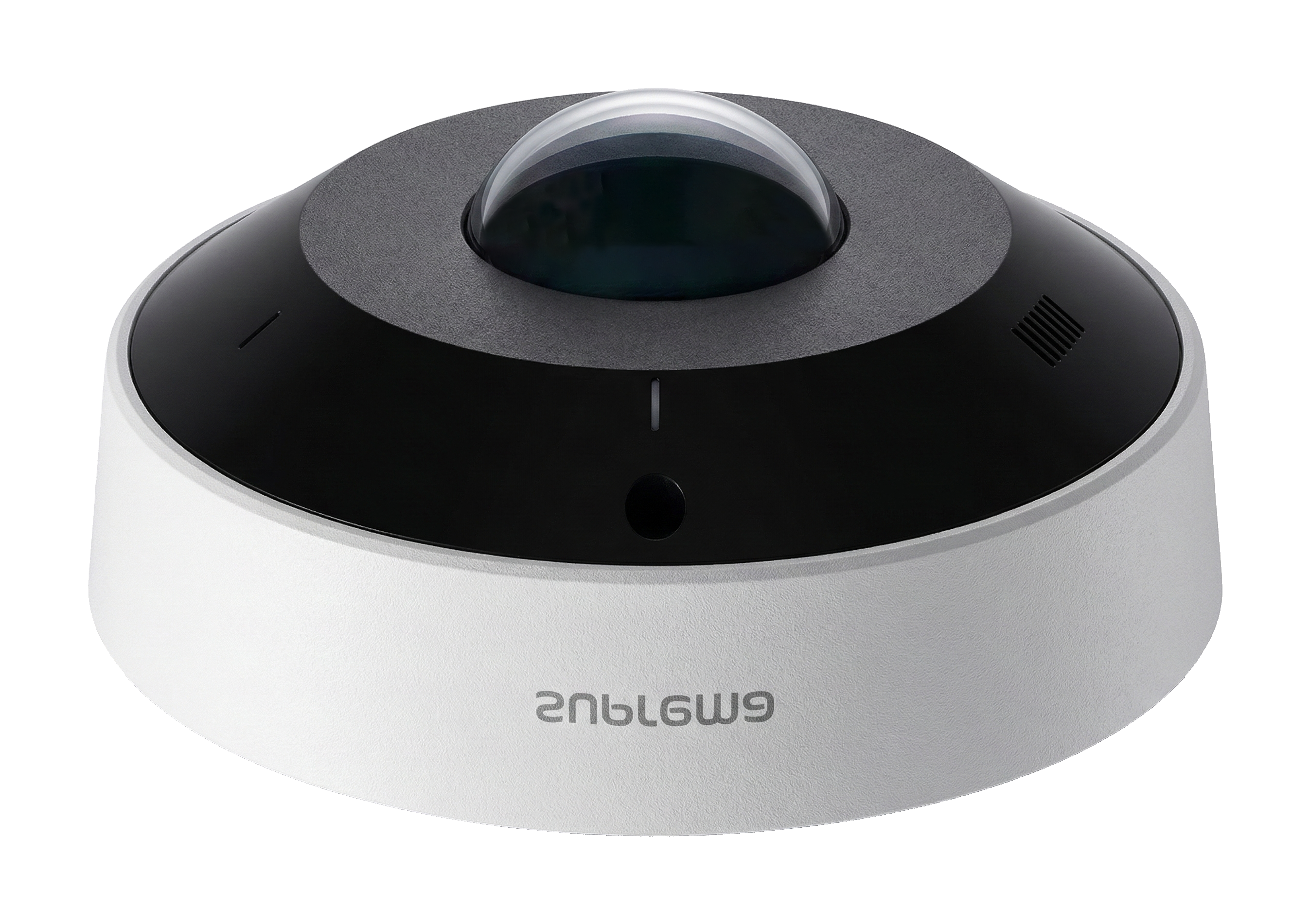
Overview of the ViOnyx camera's components, including the name and function of each part.
Components
|
|
|
|
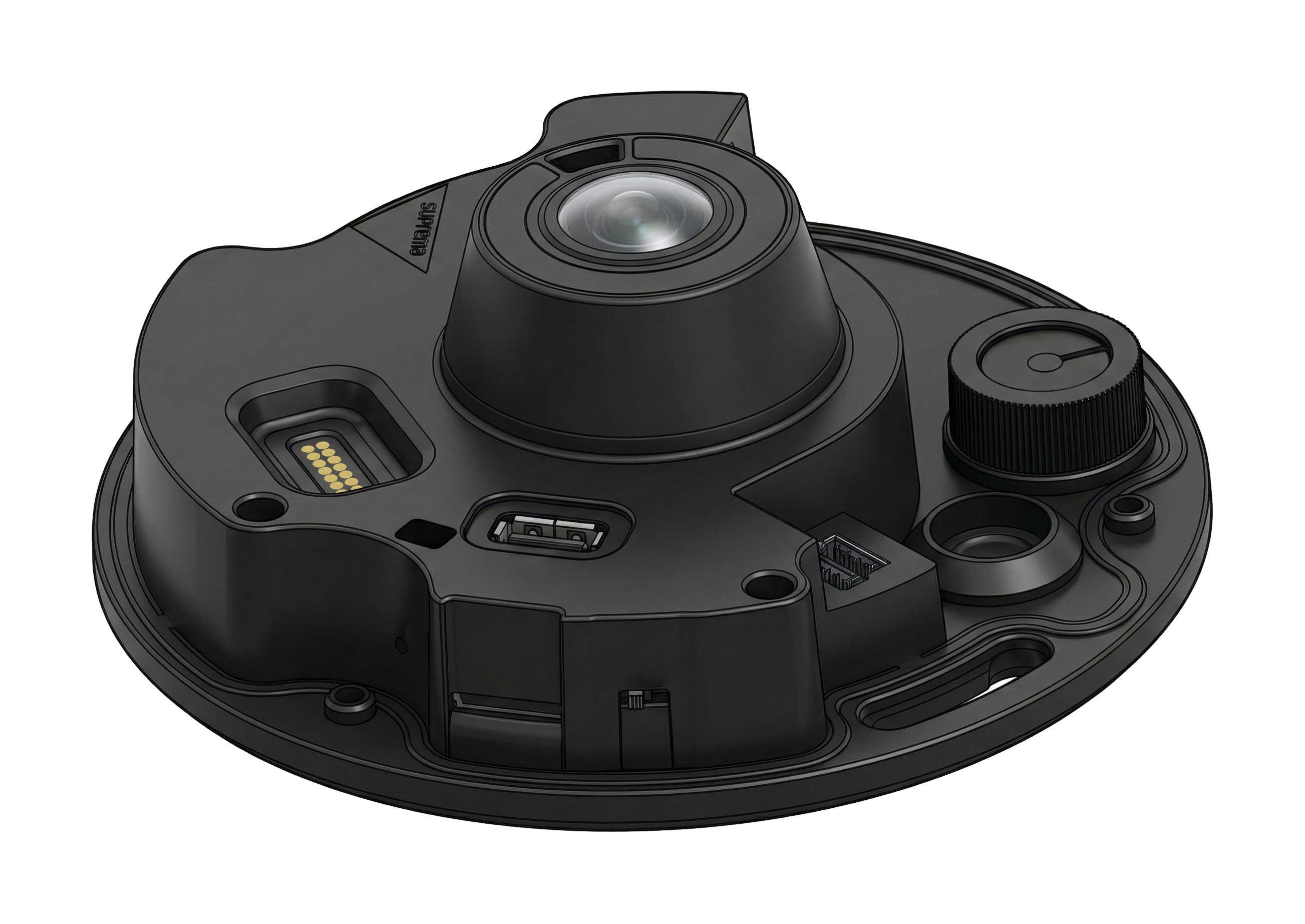
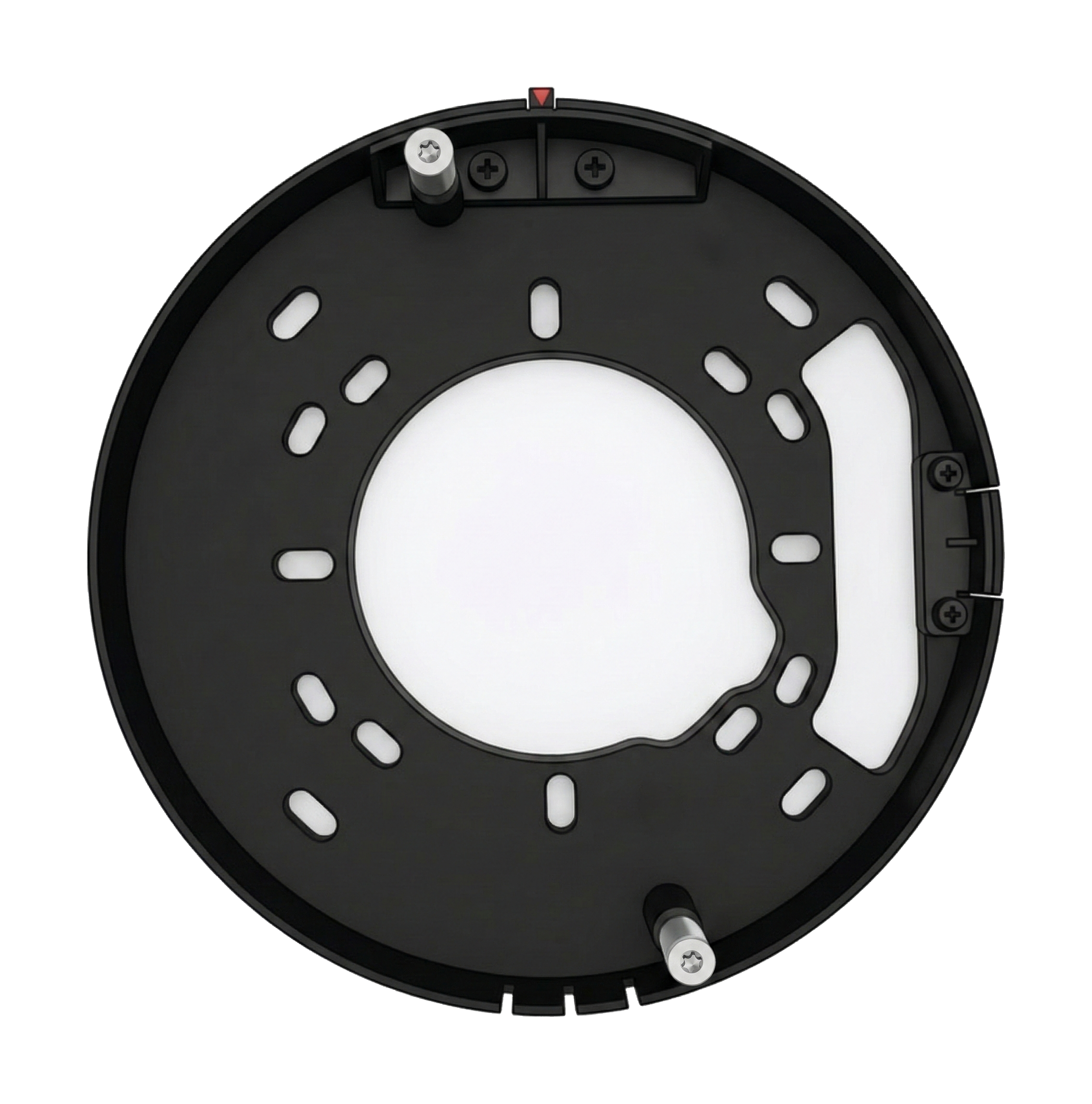
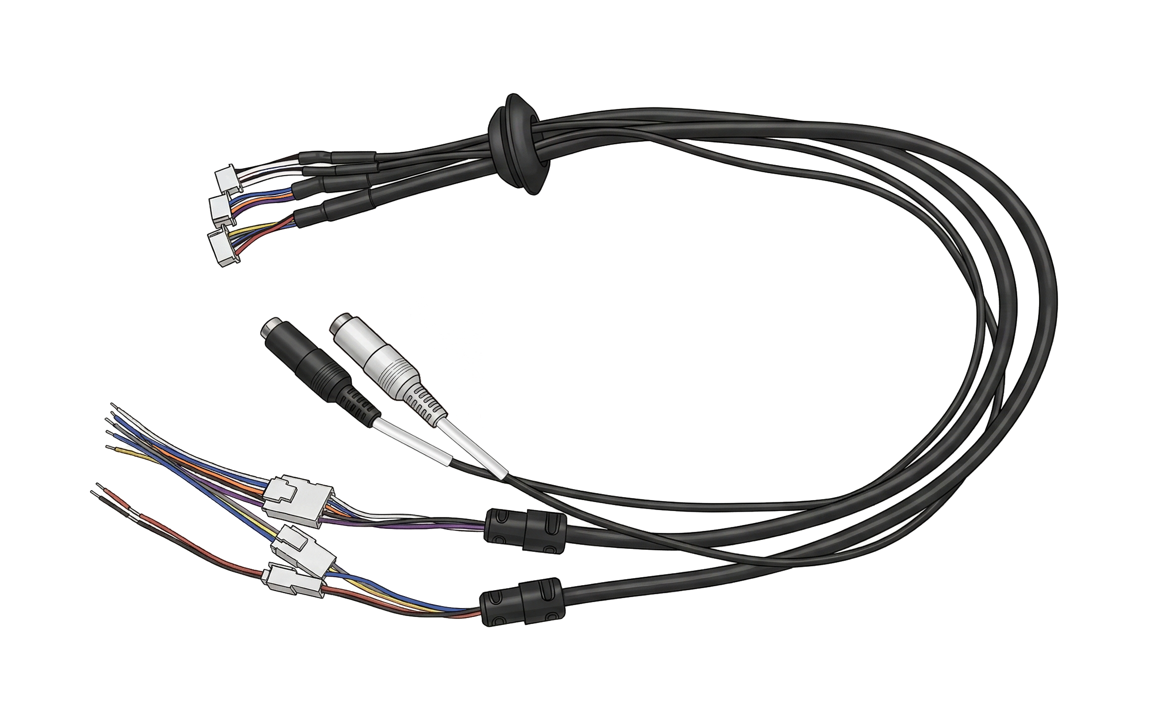
| Cover | Camera Body | Mounting Plate | Connection Cables |
|
|
|
|
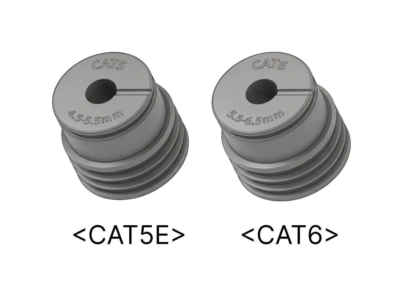
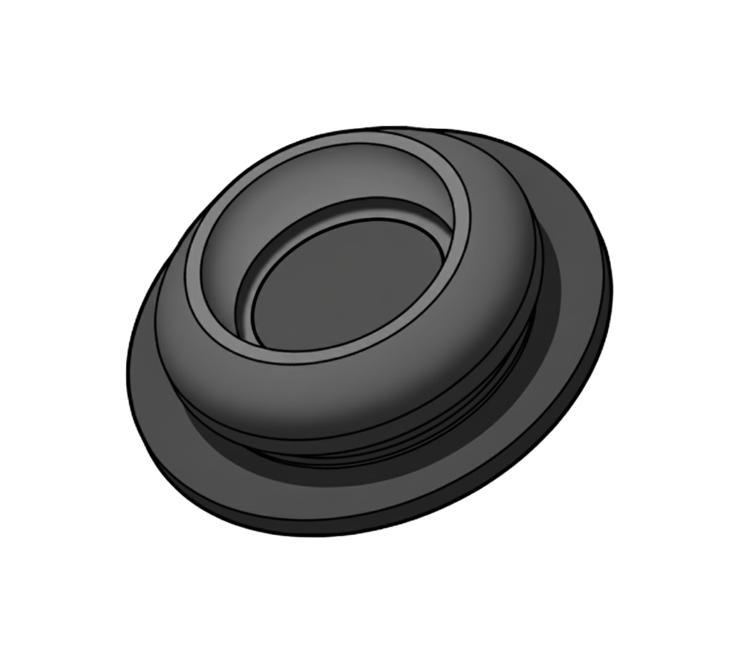
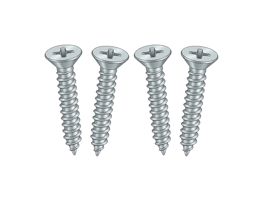
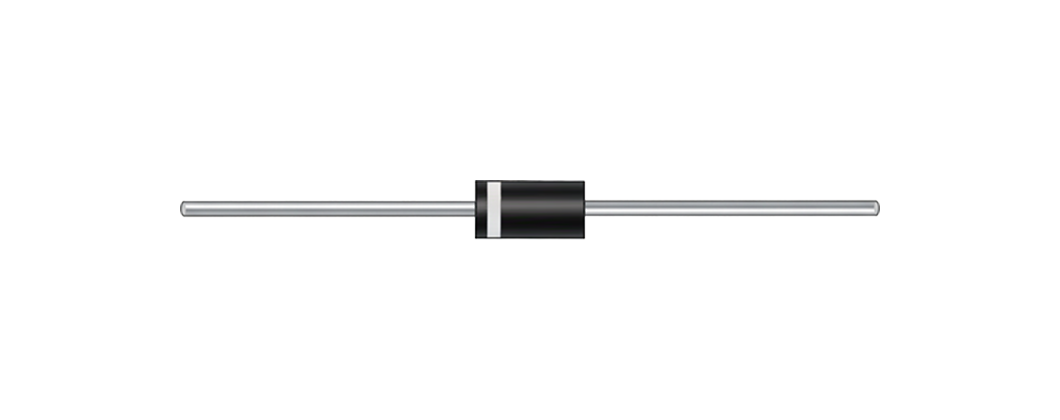
| Waterproof Grommet for Ethernet Cable | Waterproof Rubber Hole Plug | Fixing Screw x4 | Diode |
|
|
|
|
| 120 Ω Resistor | T10 Torx Driver (Star-shaped) | Quick Guide | Open Source Software Guide |


Info
- Components may vary according to the installation environment.
Name and function of each part
Internal port configuration

| Name | Function |
|---|---|
| Alarm input and relay (5-pin) | Connect the cable for alarm input and relay output. |
| Audio input/output (4-pin) | Connect the cable for audio input/output. |
| Ethernet (PoE+) | Connect the Ethernet cable. Power can be supplied via PoE+. |
| Power & RS-485 (5-pin) | Connect the cable for power and RS-485 communication. |
| Reset button | Reset all settings to factory defaults. For more information on factory initialization, refer to Factory default. |
| Micro SD card slot | Insert a microSD card. |
| USB (Type-A) | Connect USB-based accessories. |
| Microphone switch | Use the microphone switch to physically enable or disable audio recording. |
Cables and connectors
Power & RS-485

| Cable | Pin | Name | Color |
|---|---|---|---|
| POWER | 1 | PWR +VDC | Red |
| 2 | PWR GND | Black | |
| RS-485 | 3 | 485 TRXP | Blue |
| 4 | 485 TRXN | Yellow | |
| 5 | 485 GND | Gray |
Alarm input & relay

| Cable | Pin | Name | Color |
|---|---|---|---|
| ALARM_IN | 1 | ALARM IN | Purple |
| 2 | ALARM GND | Black | |
| RELAY | 3 | RLY NC | Orange |
| 4 | RLY COM | Blue | |
| 5 | RLY NO | White |
Audio input/output

| Cable | Pin | Name | Color |
|---|---|---|---|
| LINE_IN | 1 | LINE IN | White |
| 2 | LINE IN GND | Black | |
| LINE_OUT | 3 | LINE OUT | White |
| 4 | LINE OUT GND | Black |
LED Status Indicator
The LED on the front of the camera cover shows the device's operating and authentication status using colors and blinking patterns.

| LED color | Status |
|---|---|
| Green | Authentication successful |
| Red | Authentication failed |
| Blue | Normal operation |
| Blue/Green blinking | When setting DHCP to use, unable to retrieve IP address. |
Microphone switch settings (coming soon)
Use the microphone switch to physically disable the camera's microphone and prevent audio recording.

-
Audio recording is disabled by default.
-
Slide the microphone switch to the right to enable audio recording.