Installation and Connection
Provides the complete installation procedures and connection examples required for the device.
Installing the Camera
Follow the steps below to safely install the camera.
Installation Precautions
Be sure to read the following precautions before installing the camera.
-
Install the camera in a location that can support a load of at least 5 times the camera's weight.
-
Avoid pinching cables or damaging the wire insulation, as this may cause product damage or fire.
-
Keep others away from the installation area while installing the camera. Before you begin, remove any valuables or items below the installation area that could be damaged.
-
Using excessive force when assembling may cause malfunction or damage to the product. Use only the specified tools.
Waterproof and Dustproof Precautions
-
This product meets IP66 and IP67 ratings for water and dust protection, but do not install it in locations exposed to direct water spray or continuous immersion.
-
When opening the cover during installation, take care to prevent moisture or dust from entering the interior.
-
When connecting cables, make sure to properly fasten the provided waterproof components.
Installation
-
We recommend mounting the camera on the ceiling to achieve a wide field of view.
-
Do not install the camera where it will be exposed directly to sunlight or UV rays.
-
Adjust the installation location to avoid direct sunlight on the lens or strong backlighting, as these can degrade AI-based face and object recognition performance.
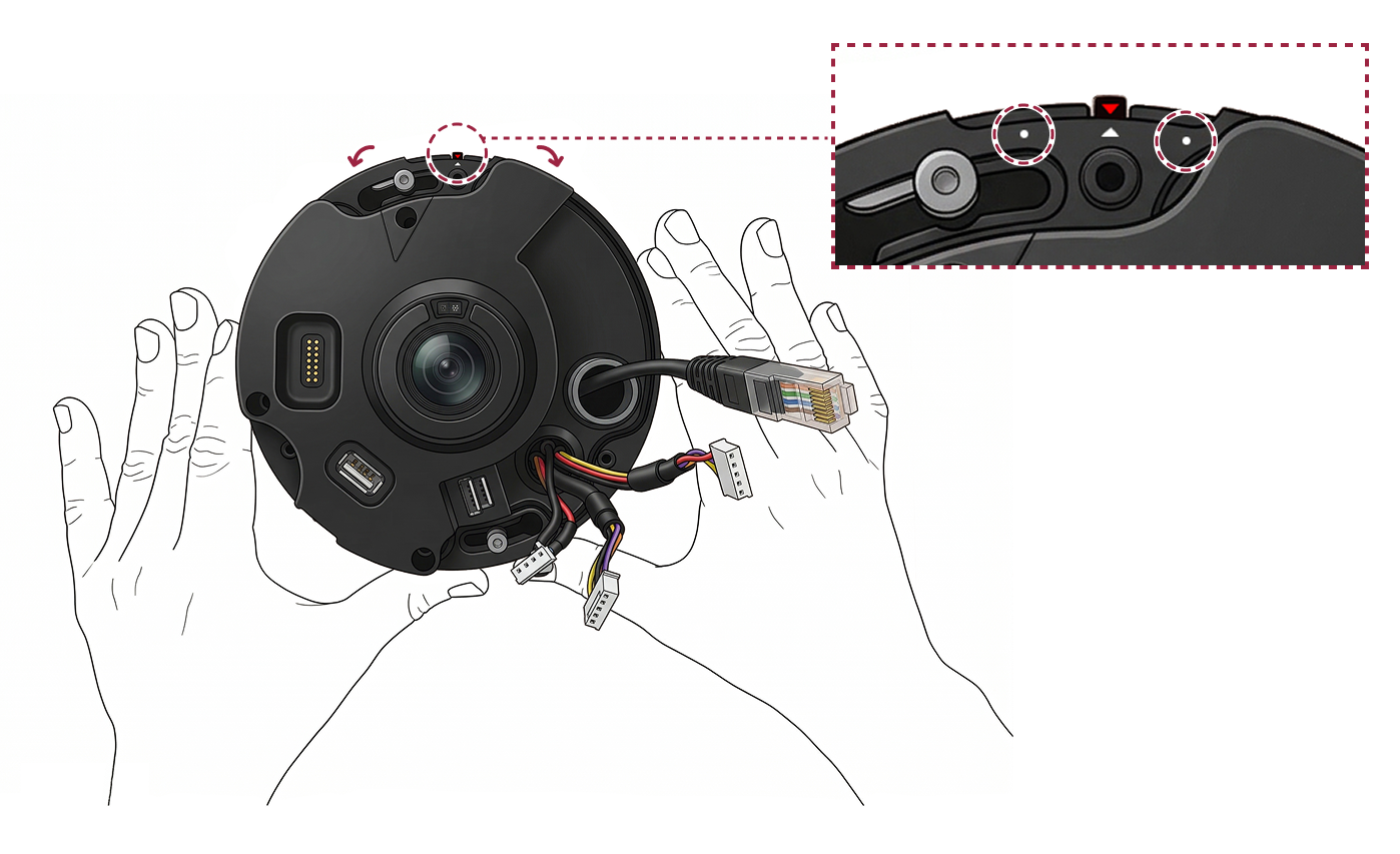
- Use the provided T10 star screwdriver to turn the screws counterclockwise and remove the camera cover.

- Loosen the mount plate's fixing screws by turning them counterclockwise, then separate the mount plate from the camera body.

- Insert a microSD card into the microSD card slot on the camera body. To connect USB (Type-A) accessories, plug them into the USB port.
-
Choose the installation location based on the camera's viewing direction.
-
When mounting on the ceiling: orient the mount plate so the AI logo faces the direction the camera will point.
-
When mounting on a wall: orient the mount plate so the red triangle points to 12 o'clock (up).
-

- Attach the provided drilling template at the installation location, then drill the screw and cable holes.

- Pass the cables to be connected (power, network, audio/alarm, etc.) through the appropriate hole in the mounting plate.

- Use the mounting screws to securely fasten the mount plate.

- Remove the Ethernet cable’s waterproof rubber and the waterproof hole plug from the camera body, then attach the required cables.

Connect the Ethernet cable
-
Slide the waterproof rubber boot for the Ethernet cable onto the Ethernet cable. Install the appropriate waterproof rubber sleeve provided for the Ethernet cable (CAT5E or CAT6).
-
Insert the Ethernet cable’s waterproof rubber into the camera body’s Ethernet hole.
-
Fasten the joint and nut onto the Ethernet cable’s waterproof rubber.

Connect other cables
Pass the cable through the hole where you removed the camera body’s waterproof hole plug, then install the waterproof rubber.

Waterproof the cable
When installing outdoors, moisture may enter through gaps in the cable connections. We recommend using commercially available butyl rubber waterproof tape and following the steps below to seal the cable connections.
-
Connect the required cables, such as power, I/O, and audio.
-
Wrap the butyl rubber tape from the cable connection to the cable jacket (part A), ensuring each layer overlaps the previous one by at least half its width.
-
If the cable jacket (part A) is not properly waterproofed, it may cause leaks. Tape it tightly with no gaps.
-
Waterproof butyl rubber tape is made of butyl rubber and can stretch to more than 2 times its original length. Stretch the tape sufficiently as you wrap it.

- Fully loosen the mount plate fixing screw, align the camera body with the center of the printed mark (red triangle), then turn the bracket fixing screw clockwise to secure it.

If you need to adjust the camera angle, rotate the camera body left or right to set the installation angle up to 15° total (up to 8° to each side).
- Use a T10 Torx driver to firmly tighten the bracket fixing screw again.

- To prevent reduced camera performance, wipe any dirt or oil from the inside and outside of the lens and cover with a soft, dry cloth.

- Attach the cover to the camera body and use a T10 Torx driver to firmly secure the 3 screws.

Fully tighten the screws when securing the cover; otherwise, waterproofing may be compromised. (IP66/IP67)
Cable connection and setup
Power supply connection

-
Do not connect the power supply (or adapter) and the PoE+ power source at the same time.
-
Use a power adapter approved to IEC/EN 62368-1 with an output rating equal to or greater than the camera's maximum power consumption. If you plan to connect another device to the power adapter, use an adapter with a capacity equal to or greater than the combined power consumption of the camera and the other device.
- Refer to the Power section in the product specifications for maximum current consumption.
-
When connecting the power supply, be aware of the distance between the device and the power supply. The device should be connected as close as possible to the power supply so that the length of the connecting cable is kept to a minimum. If cable connections are made improperly it may cause the device to malfunction. It is recommended to use a 16 AWG or 18 AWG cable if the product is far from the power supply. This product uses a rated voltage of 12Vdc. Do not apply power above the rated voltage, as this may damage the product. Check the maximum extension length for each cable specification and connect the power correctly.
Cable standard Max. extended length 16 AWG 50 m 18 AWG 30 m 20 AWG 20 m -
DO NOT extend the length of power cable when using the power adapter.
Network Connection
TCP/IP: LAN connection (connect to a hub)
-
You can connect to the hub using a standard CAT-5e cable.
-
Supports PoE+, which provides both power and data over a single Ethernet cable.

Network ports and services
This device uses the following ports for network communication and stable service operation.
| Protocol | Service Description |
|---|---|
| TCP | Used for communication services between the server and the device, and for the device operation status switching service. |
| UDP | Used for the device discovery service to search for devices on the network. |
These ports are required for the product's normal network operation. When configuring firewall or network security settings, allow traffic through these ports.
RS-485 connection (coming soon)
Connect to external devices via RS-485. Observe the polarity (A/B) when wiring.
-
Use an AWG24 twisted pair with a maximum length of 1.2 km for the RS-485 cable.
-
It is recommended to use RS-485 cables with a characteristic impedance of 120 Ω.
-
If connecting with a RS-485 daisy chain, connect the termination resistor (120 Ω) to both ends of the daisy chain connection. If connected to the middle line, the signal level becomes smaller and the communication performance will deteriorate. Make sure to connect it to both ends of the daisy chain connection.

Alarm input connection
This is an input port that receives signals from external sensors or switches.

Relay Connection
Fail Safe Lock
In order to use the Fail Safe Lock, connect N/C relay as shown in the figure below. There is normally a current flowing through the relay for the Fail Safe Lock. When the relay is activated, blocking the current flow, the door will open. If the power supply to the product is cut off due to a power failure or an external factor, the door will open.

-
Install diodes on both sides of the wiring as shown to protect the relay from reverse current generated when a door lock or strobe light activates.
-
External devices connected to the product (e.g., door locks) must use a separate power supply.
-
Suprema’s standalone intelligent readers contain internal relays that can directly lock/unlock doors without external controllers for added convenience. For access control applications in need of security, however, it is NOT recommended to use the internal relay of a reader to prevent any tampering attacks which can potentially trigger the door unlock. For such applications, it is highly recommended to use a separate relay unit for a lock control such as Suprema’s Secure I/O 2, DM-20 or CoreStation installed at a secure side of a door.
Take caution of the installation direction of the diode. Install the diode as close as possible to the connected external device.
Fail Secure Lock
In order to use the Fail Secure Lock, connect N/O relay as shown in the figure below. There is normally no current flowing through the relay for the Fail Secure Lock. When the current flow is activated by the relay, the door will open. If the power supply to the product is cut off due to a power failure or an external factor, the door will lock.

-
Install diodes on both sides of the wiring as shown to protect the relay from reverse current generated when a door lock or strobe light activates.
-
External devices connected to the product (e.g., door locks) must use a separate power supply.
-
Suprema’s standalone intelligent readers contain internal relays that can directly lock/unlock doors without external controllers for added convenience. For access control applications in need of security, however, it is NOT recommended to use the internal relay of a reader to prevent any tampering attacks which can potentially trigger the door unlock. For such applications, it is highly recommended to use a separate relay unit for a lock control such as Suprema’s Secure I/O 2, DM-20 or CoreStation installed at a secure side of a door.
Take caution of the installation direction of the diode. Install the diode as close as possible to the connected external device.
Automatic door connection

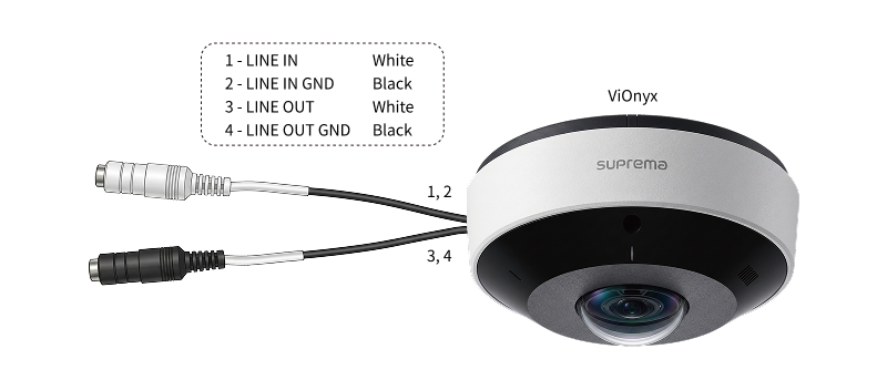
Audio connection (coming soon)
-
Audio input (LINE IN): Connect an audio source. The product includes a built-in microphone on the front.
-
Audio output (LINE OUT): Connect to an amplifier. This product does not include a built-in audio amplifier; use a separate amplifier and speakers.
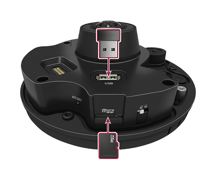
Micro SD card and USB device connection (coming soon)
-
Micro SD card: Insert a microSD card to record video.
-
USB: Connect other USB (Type-A) accessories.
Recommended microSD/SDHC/SDXC card specifications
-
Recommended capacity: 16GB to 1TB
-
We recommend using memory cards from the following manufacturers and product lines.
-
Manufacturers: Samsung, SanDisk, Transcend, Micron
-
Product lines: High Endurance, Pro Endurance
-
-
Compatibility may vary by card manufacturer and type.