Installation
Provides the complete installation procedures and connection examples required for the device.
Fixing the bracket and the product
-
Secure the bracket tightly using the fixing screws at the location where the product will be mounted.
 Info
Info-
If installing the product on a concrete wall, drill a hole, insert a PVC anchor, and secure it with a fixing screw.
-
To avoid RF interference, a minimum separation distance must be maintained.
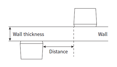
Wall thickness Distance 100 mm 270 mm 120 mm 250 mm 150 mm 170 mm 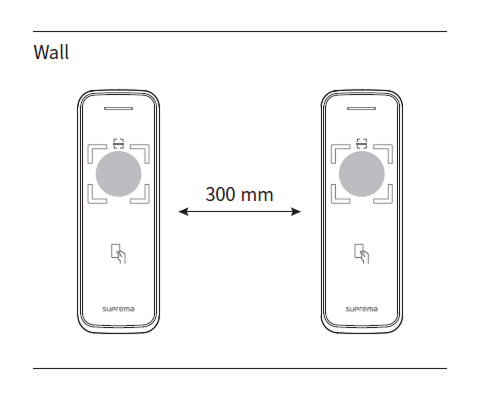
- When using a mobile access card, install devices maintaining a minimum distance of 1 m between devices to avoid BLE interference.
-
-
Tighten the four screws securing the cable cover.
 Info
InfoMake sure that the cable cover is completely closed after connecting it to the product to maintain the water-resistant and dust-resistant features (IP65 rating).
-
Mount the product on the fixed bracket.

-
Rotate the fixing screws to assemble the product with the bracket.
 Info
InfoWhen assembling the product with the bracket, you can use the included bracket fixing screw (Star Shaped) instead of the product fixing screw for enhanced security.
Power supply connection
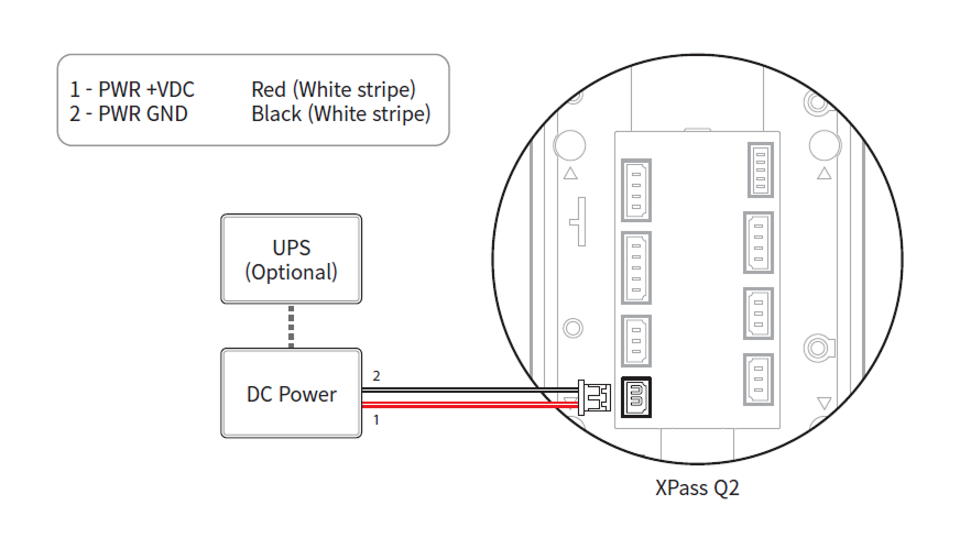
-
Use the IEC/EN 62368-1 approved power adapter that supports higher power consumption than the product. If you wish to connect and use another device to the power supply adapter, you should use an adapter with a current capacity which is the same or larger than the total power consumption required for the terminal and another device.
- Refer to the Power in the product specifications for maximum current consumption specifications.
- Use a separate power supply for Secure I/O 2, the electric lock, and the product respectively. If connecting and using the power supply to these devices together, the devices may malfunction.
- DO NOT extend the length of power cable when using the power adapter.
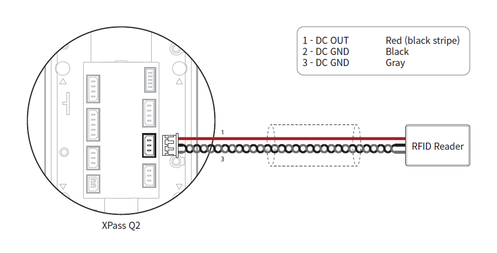
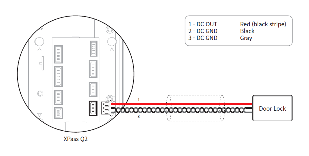
Connect reader and lock power
Connect reader power
Connect lock power
Power-specific reader and lock power specifications
| Power | Maximum reader current | Maximum lock current |
|---|---|---|
| DC 12V | 500 mA | 1.2 A |
| DC 24V | 250 mA | 600 mA |
Maximum extension length by cable specification
The distance that can be connected may vary depending on the cable specifications and installation environment used for power connection. If cable connections are made improperly it may cause the device to malfunction. This product supports both DC 12V and DC 24V power supplies, so check the maximum extension length according to each cable specification and connect the power correctly.
| Cable specifications | DC 12V | DC 24V | ||
|---|---|---|---|---|
| Reader (500 mA) | Lock (1.2 A) | Reader (250 mA) | Lock (600 mA) | |
| 14 AWG | 190 m | 95 m | 770 m | 385 m |
| 16 AWG | 120 m | 60 m | 480 m | 240 m |
| 18 AWG | 75 m | 35 m | 300 m | 150 m |
The actual maximum extension length can vary depending on the resistance of the cable manufacturer and model.
Network Connection
TCP/IP
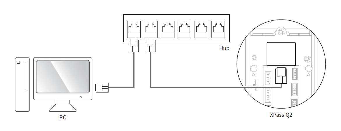
LAN connection (connecting to a hub)
You can connect to the hub using a standard CAT-5e cable.
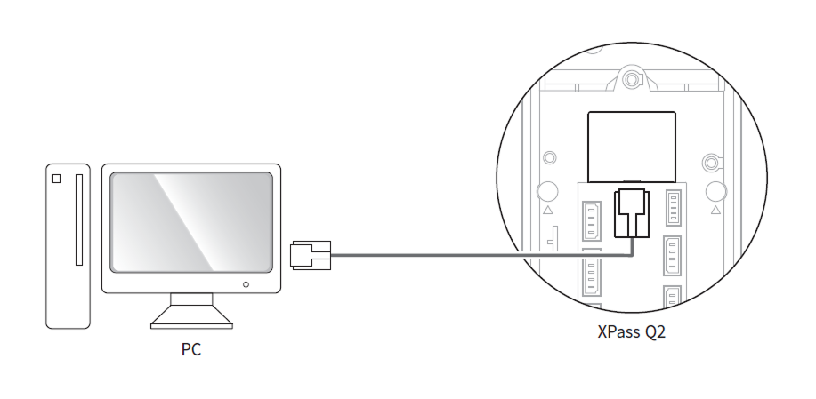
LAN connection (connecting to a PC directly)
-
This device features automatic MDI/MDIX, so it can connect directly to a PC using either a cross cable or a standard straight CAT-5e cable.
CautionCertain non-standard hubs/switches may not support automatic MDI/MDIX.
Network ports and services
This device uses the following ports for network communication and stable service operation.
| Protocol | Service Description |
|---|---|
| TCP | Used for communication services between the server and the device, and for the device operation status switching service. |
| UDP | Used for the device discovery service to search for devices on the network. |
These ports are used to provide normal network features of the product. When configuring firewall rules or network security settings, allow the use of these ports.
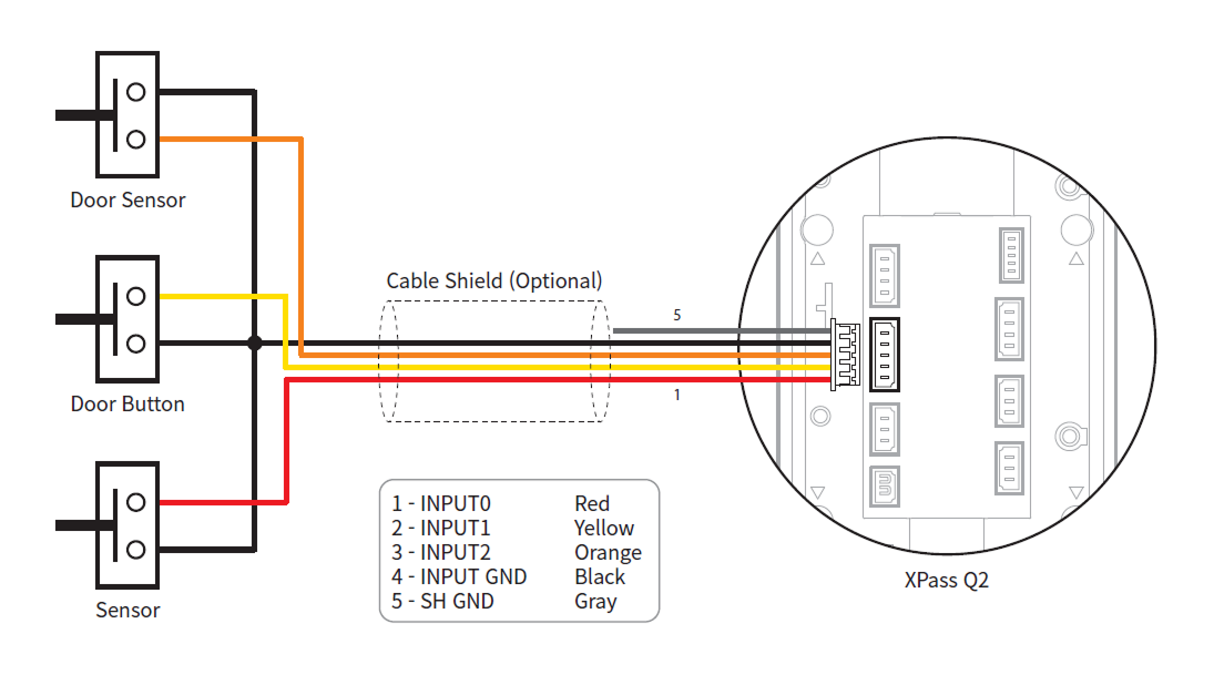
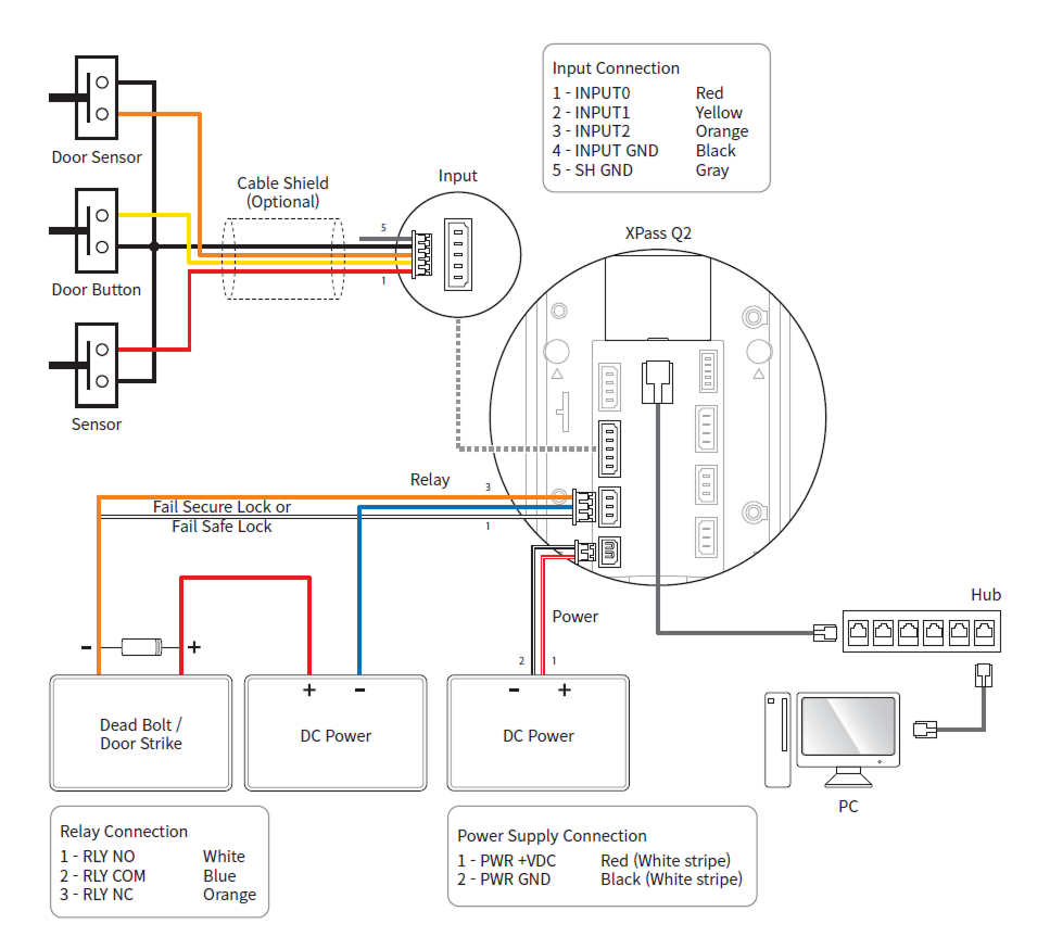
Input connection
Relay Connection
Fail Safe Lock
In order to use the Fail Safe Lock, connect N/C relay as shown in the figure below. There is normally a current flowing through the relay for the Fail Safe Lock. When the relay is activated, blocking the current flow, the door will open. If the power supply to the product is cut off due to a power failure or an external factor, the door will open.
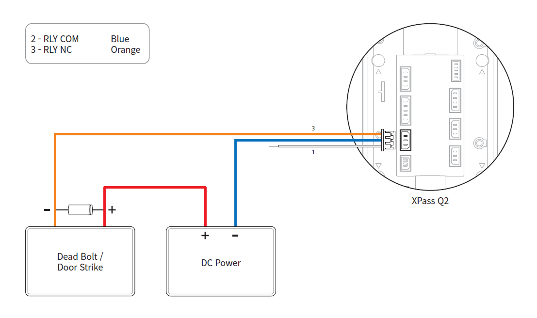
-
Install a diode at both sides of the door lock wire as shown in the figure to protect the relay from the reverse current, which occurs when the door lock operates.
-
Use a separate power supply for the product and the door lock.
-
Suprema’s standalone intelligent readers contain internal relays that can directly lock/unlock doors without external controllers for added convenience. For access control applications in need of security, however, it is NOT recommended to use the internal relay of a reader to prevent any tampering attacks which can potentially trigger the door unlock. For such applications, it is highly recommended to use a separate relay unit for a lock control such as Suprema’s Secure I/O 2, DM-20 or CoreStation installed at a secure side of a door.
Take caution of the installation direction of the diode. Install the diode close to the door lock.
Fail Secure Lock
In order to use the Fail Secure Lock, connect N/O relay as shown in the figure below. There is normally no current flowing through the relay for the Fail Secure Lock. When the current flow is activated by the relay, the door will open. If the power supply to the product is cut off due to a power failure or an external factor, the door will lock.
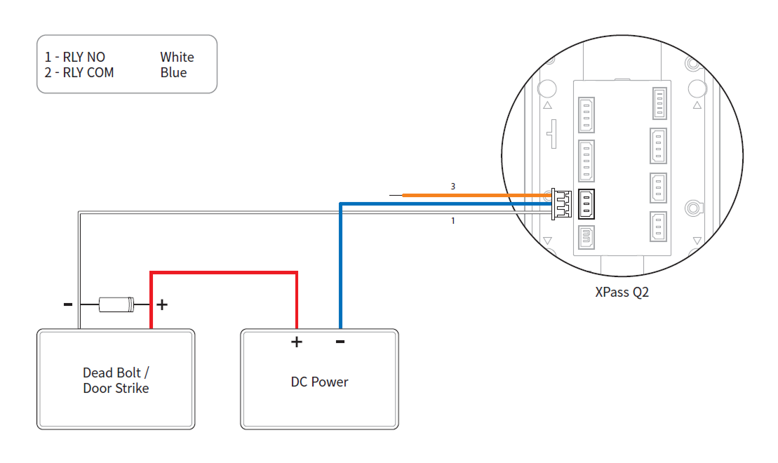
-
Install a diode at both sides of the door lock wire as shown in the figure to protect the relay from the reverse current, which occurs when the door lock operates.
-
Use a separate power supply for the product and the door lock.
-
Suprema’s standalone intelligent readers contain internal relays that can directly lock/unlock doors without external controllers for added convenience. For access control applications in need of security, however, it is NOT recommended to use the internal relay of a reader to prevent any tampering attacks which can potentially trigger the door unlock. For such applications, it is highly recommended to use a separate relay unit for a lock control such as Suprema’s Secure I/O 2, DM-20 or CoreStation installed at a secure side of a door.
Take caution of the installation direction of the diode. Install the diode close to the door lock.
Automatic door connection
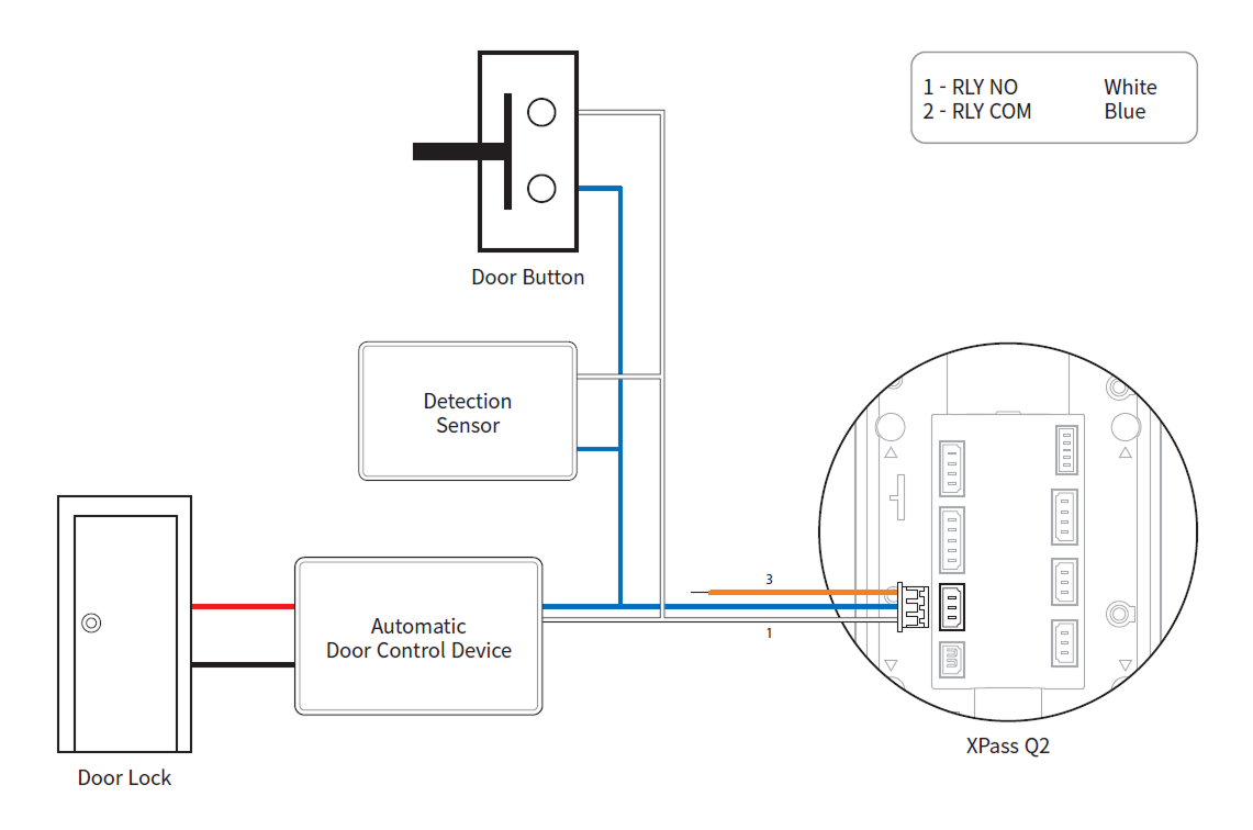
Connecting as a Standalone
The product can be connected to the door lock, door button, and door sensor directly without connecting a separate I/O device.
Suprema’s standalone intelligent readers contain internal relays that can directly lock/unlock doors without external controllers for added convenience. For access control applications in need of security, however, it is NOT recommended to use the internal relay of a reader to prevent any tampering attacks which can potentially trigger the door unlock. For such applications, it is highly recommended to use a separate relay unit for a lock control such as Suprema’s Secure I/O 2, DM-20 or CoreStation installed at a secure side of a door.
- The device can be used as a multi-door controller with the slave devices with the RS-485 cable. The slave devices are used as dummy readers and authentication is performed in the master device.
- When this product operates as a master, only card or QR/Barcode authentication is available on the slave.
- Connect up to 31 slave devices to a master device.
- For more information, contact the Suprema Technical Support Team.
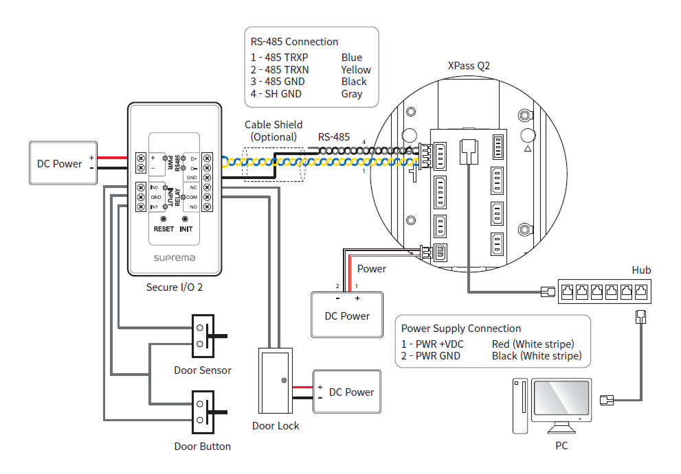
Connecting to Secure I/O 2
Secure I/O 2 is an I/O device, can be connected to the product with the RS-485 cable. Security can be maintained even if the connection between the product and Secure I/O 2 has been lost or the power supply to the product has been shut off due to external factors.
-
Use an AWG24 twisted pair with a maximum length of 1.2 km for the RS-485 cable.
-
It is recommended to use RS-485 cables with a characteristic impedance of 120 Ω.
-
If connecting with a RS-485 daisy chain, connect the termination resistor (120 Ω) to both ends of the daisy chain connection. If connected to the middle line, the signal level becomes smaller and the communication performance will deteriorate. Make sure to connect it to both ends of the daisy chain connection.
- The device can be used as a multi-door controller with the slave devices with the RS-485 cable. The slave devices are used as dummy readers and authentication is performed in the master device.
- When this product operates as a master, only card or QR/Barcode authentication is available on the slave.
- Connect up to 31 slave devices to a master device.
- For more information, contact the Suprema Technical Support Team.
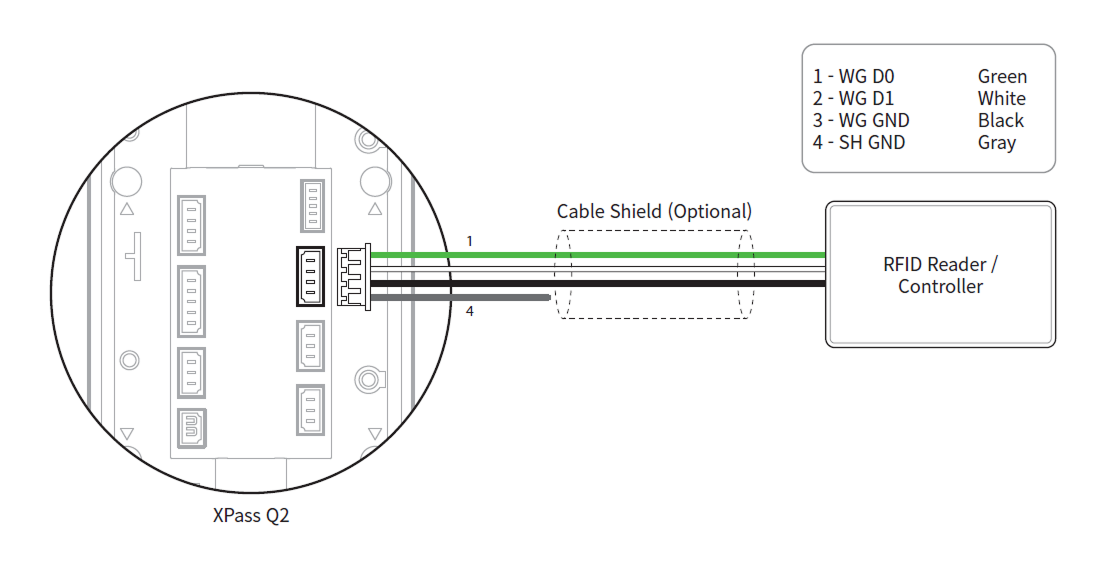
Wiegand Connection
Use as a Wiegand input or output device.
Initialize Network Settings
Initialize the device's network settings.
-
Power on.
-
Press the reset button until the device automatically reboots.
-
Connect the device using the initialized network information.
-
TCP/IP Address: DHCP address assignment (if DHCP address assignment fails, will be set to 169.254.x.x).
-
Server Mode: Disable
-
RS-485: Default, 115200 bps
-
-
Change the TCP/IP or RS-485 information.
-
Check if the network information is correctly set after turning the power off and on.
Factory default
Delete all information stored on the device and initialize the settings.
-
Power on.
-
Quickly press the reset button three times.

-
Press the reset button once more when the device's LED blinks green.
You can only use Factory Default when the root certificate is stored on the device.
Firmware upgrade
You can connect a USB memory stick to upgrade the firmware.
-
Save the firmware file to a USB memory stick for upgrade.
InfoIt is recommended to save only one firmware file on the USB memory stick for the upgrade.
-
Connect the USB memory stick to the device.
InfoAuthentication is temporarily suspended while the USB memory is being read.
-
When the LED/buzzer indicates an authentication request, authenticate with an administrator credential.
Info-
Register the administrator on BioStar X for the device. You cannot proceed with the firmware upgrade if an administrator is not registered on the device. For detailed instructions on how to register an administrator, please refer to the BioStar X Administrator Guide.
-
Only one authentication attempt is allowed per USB memory insertion.
-
If authentication fails, the LED/buzzer indicates the failure and USB reading ends. Disconnect the USB memory and reconnect it to the device.
-
-
After successful administrator authentication, the device performs a firmware upgrade and indicates the upgrade with the LED.
InfoIf the firmware file is missing or corrupted, the upgrade does not proceed and the LED/buzzer indicates failure.
-
The device restarts automatically after the firmware upgrade is complete.
Do not disconnect the power supply while upgrading the firmware of the device. The device may malfunction.